ABYC Standards Outline Corrosion Protection
The corrosion protection systems that boat builders put in place must adhere to ABYC standards if a boat is going to be NMMA certified. This will not only help keep the boat in good operating condition, but aspects of the standard also head off the problems of improperly designed – or installed – bonding systems that can actually increase galvanic corrosion.
Boat Building Standards:
Cathodic Protection
ABYC Standards—
Notes:
1. The negative potential (e.g., -1050 mV as compared to silver/silver chloride reference electrode) that can be achieved by some corrosion-control systems will result in some decrease in effectiveness of anti-fouling paints. Because the decrease in effectiveness increases with higher negative voltages, the negative potential should be kept as close to the optimum value as possible (see TABLE II). A reference potential reading in excess of -1100 mV indicates excessive cathodic protection.
2. The need for a cathodic protection system for metal appendages on non-metallic hulls may not be justified if the metals coupled are galvanically compatible (see TABLE II); however, individual testing on a case by case basis is necessary.
Note: Coating of cathodic metal surfaces may be used to achieve the relationship.
- A cathodic protection system shall be capable of inducing and maintaining a minimum negative shift of 200 mV relative to the corrosion potential of the least noble metal being protected.
- Hull-mounted metallic trim tabs — On boats equipped with aluminum drive systems, metallic trim tabs shall be installed in accordance with the manufacturer’s instructions, and may be isolated from the boat's cathodic bonding system to reduce the load on the boat's cathodic protection system.
- Metallic trim tabs shall be electrically isolated from their electrically actuated mechanisms, in accordance with DC electrical system standards.
- If a metallic trim tab system is connected to a boat's cathodic bonding system, the cathodic protection system's output rating shall be increased to provide the additional required protection.
- An effective method of cathodic protection shall be provided to all components of a metallic trim tab assembly.
- Immersed cathodic metal surfaces shall be favorably matched in anode to cathode area relationship.
- Coatings — If anti-fouling coatings containing pigments that are galvanically incompatible with the substrate metal are used, then cathodic protection shall be maintained and a barrier coating shall be used between the anti-fouling coating and the substrate.
Note: Prior to the application of a barrier coating on metallic surfaces, the surface should be tested for the presence of soluble salts. If salts are present on a surface, they should be reduced to an acceptable level of three micrograms per square centimeter prior to the application of a barrier coating. Special solutions for the reduction of soluble salts, as well as test kits are commercially available.
- Coatings on surfaces shall be capable of tolerating alkali generated by the cathodic protection system.
- Anode Placement — Anodes shall be mounted on a surface that cannot entrap gas bubbles.
- Anodes shall be located so as not to disturb the flow of water past the propeller(s) or jet drive intake and nozzle(s).
- Anodes shall be mounted so as not to disturb water flow near intakes and discharge fittings.
Notes:
1. An electrical resistance greater than one ohm will degrade cathodic protection system performance.
2. Propeller shafts do not provide reliable electrical continuity to the boat's cathodic bonding system.
3. Resistance measurements should only be taken when the boat is out of the water.
4. Hull potential measurements using a reference electrode should be used to determine cathodic bonding system integrity when the boat is in the water.
- Sacrificial anodes and reference electrodes shall be installed to avoid areas marked for lifting slings and chocks.
- All metals that are to receive cathodic protection from the cathodic protection system shall have a maximum resistance of one ohm to the cathodic bonding system anode.
- Rudderposts shall be cathodically bonded by means of a flexible conductor positioned to allow full rudder movement without stressing the cathodic bonding conductor or its connection.
Cathodic Bonding Conductors
Exception: Wiring provided by engine and drive manufacturers contained on the engine/drive system.
Note: These requirements are based on physical strength, the ability to make and maintain low-resistance connections, and current ratings.
- Cathodic bonding conductors shall be oil resistant insulated, tinned, stranded copper wire, or uninsulated copper strip. Copper braid or copper tubing shall not be used for this purpose.
- Uninsulated copper strip, metal mounting hardware, and terminal hardware shall not be in direct contact with wood.
- Connections to the uninsulated copper strip shall comply with standards regarding AC and DC electrical systems.
- Wire, where used as a cathodic bonding conductor, shall be at least #8 AWG, or where the cathodic bonding system is used as a part of the lightning protection system, this conductor shall not be less than the equivalent of #6 AWG (in accordance with the lightning-protection standard).
- Cathodic bonding conductors fabricated from a copper strip shall have a minimum thickness of 1/32 inch (0.8 mm) if connections are through-bolted and a minimum width of 1/2 inch (13 mm), or connections using machine screws shall have a minimum thickness sufficient to allow for the engagement of four threads at connections if drilled and tapped, and a minimum width of 1/2 inch (13mm).
- Self-tapping fasteners shall not be used at connections.
- Insulated conductors shall be selected from standrards regarding AC and DC electrical systems.
- Insulated conductors shall be identified by the color green or green with yellow stripe(s).
- Shaft brushes used to provide cathodic protection shall be constructed of materials which will not score the shaft at the shaft-to-brush contactor.
- A metal hull shall be connected directly to the engine negative terminal, and the connection shall be made above the normal accumulation of bilge water, and if a lightning protection system is installed on the boat, this conductor shall not be less than the equivalent of #6 AWG (in accordance with the lightning-protection standard).
Galvanic Isolation
Note: It is strongly recommended that any boat with a permanently installed shore power system be provided with galvanic isolation. Galvanic isolation may be achieved by use of a galvanic isolator, polarization transformer with galvanic isolator, or an isolation transformer. The electrical interconnection that occurs via shore power grounding conductor may result in the flow of galvanic current between the boat and dock structure or another boat. This can lead to excessive anode loss, or corrosion beyond the capacity of the boat's cathodic protection system.
- If installed, galvanic isolators shall be installed in accordance with their own standard.
- If installed, isolation transformers shall be installed in accordance with AC and DC electrical systems.
Sacrificial Anodes
- If installed, the mass and exposed surface area of the anode(s) used to achieve cathodic protection (e.g.,magnesium, zinc, aluminum,) shall be sufficient to provide continuous current output or capable of inducing and maintaining acceptable potential levels according to E-2.5.1 for at least the period between inspections.
Notes:
1. Inspections may be conducted at intervals suitable for the usage and location of the boat, generally annually.
2. Typical compositions of zinc, aluminum, and magnesium anodes are listed in ABYC standards. Zinc anodes require zinc of high quality with the most undesirable (critical) trace element being iron. The addition of cadmium and aluminum will permit an increase in the tolerance for iron. Zinc anodes have a natural potential approximately -1050 mV with reference to a silver/silver chloride reference electrode in seawater.
3. The fixed potential of sacrificial anodes provides their basic utility, but the available current depends upon the exposed surface and the necessary mass to maintain this current over a period of time.
4. Anodes may be selected based upon location of the boat.
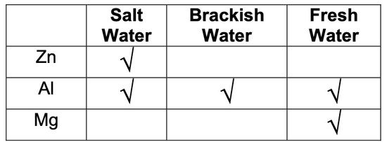
6. Zinc or aluminum galvanic anodes may be applied directly to aluminum, steel and non-metallic hulls without shielding.
- Sacrificial anodes on a shaft shall be installed so as not to restrict water flow to strut bearings.
Note: Collars applied to the propeller shaft of boats are usually adequate to protect the propellers and shafts of bronze and stainless steel.
- Magnesium hull anodes installed on steel or aluminum hulls shall have a dielectric shield installed between the anode and the hull.
- Each anode shall have a single point of connection to the bonding system.